Project Description
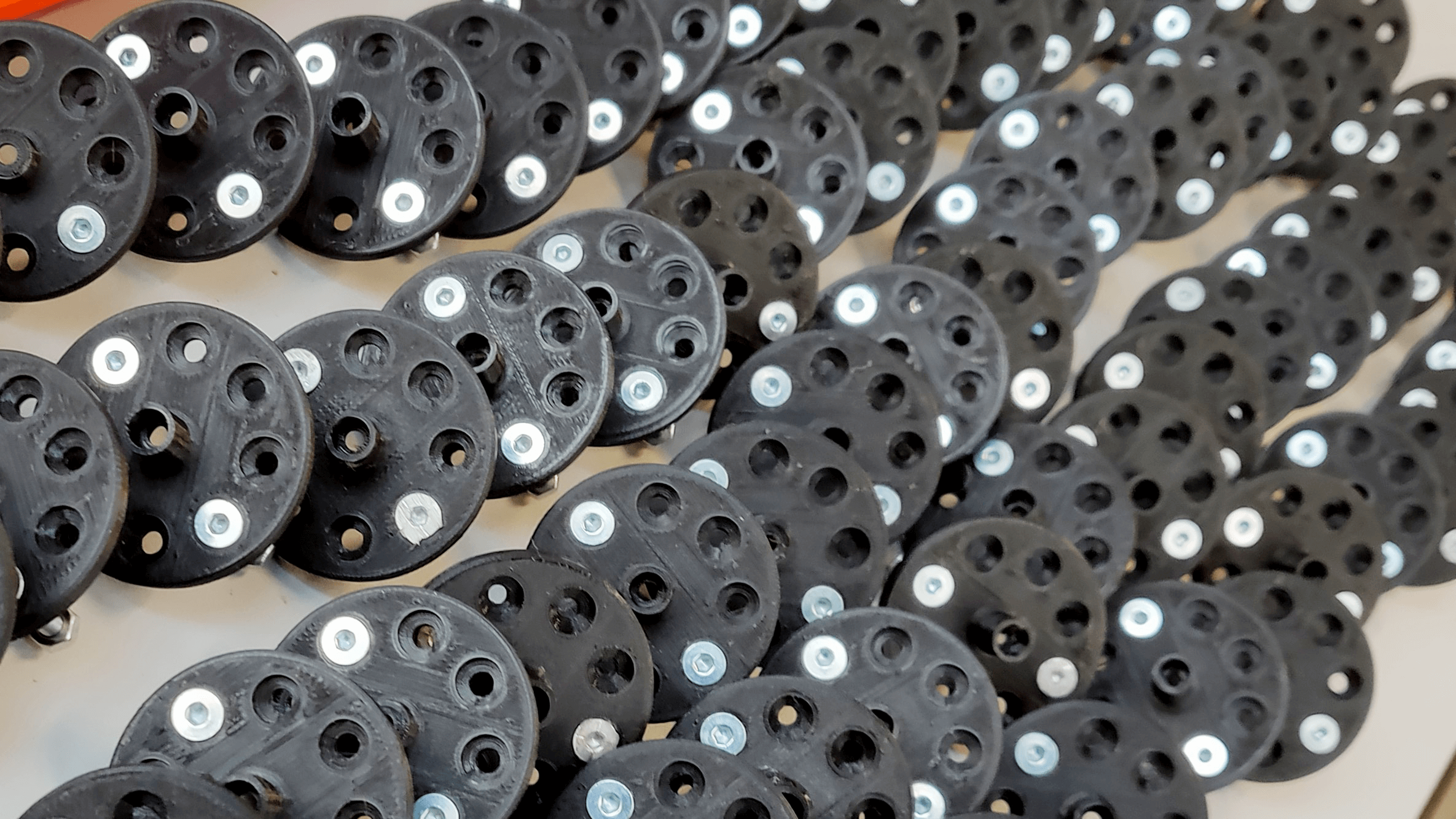
M.A.T.S. is a programmable control unit for the production of customizable cladding elements. The system is structured around one or more template boards (grid of freely rotating customizable pegs) whose configuration can be modified with an external programmer board (grid of programmable rotating servo motors). The combination of the two elements allows to manufacture multiple variations of the same template rapidly, making it an ideal solution for large scale claddings.
images courtesy of INDEXLAB
System Overview
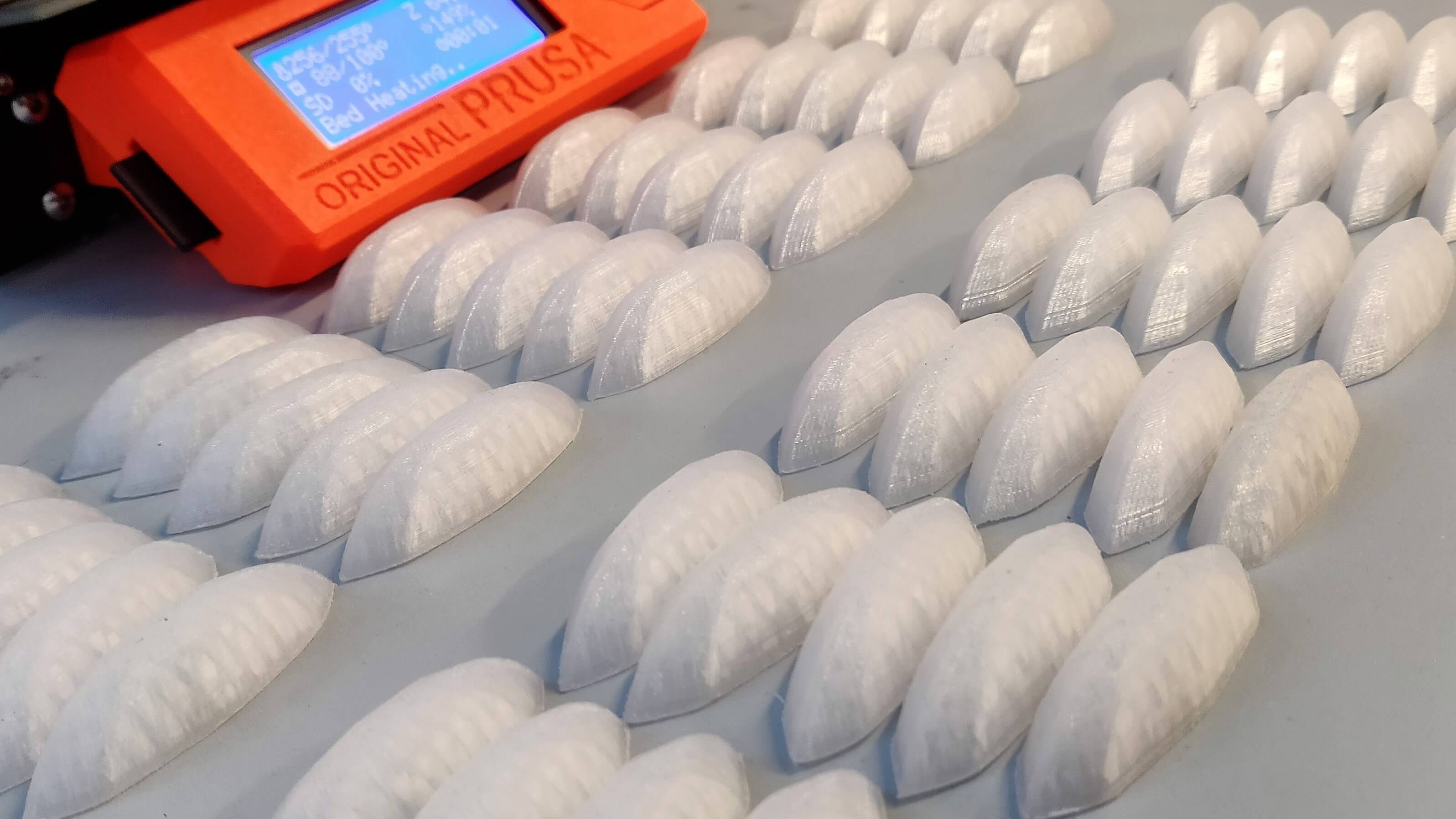
The process begins with the template board configured in a home position where the rotating pegs are aligned. The programmer unit descends on the template board interlocking each peg with the equivalent servo motor. Each peg is rotated to match the panel design and once completed the programmer unit is lifted releasing the template board. Each configurated template board can be used as a mold for the vacuum forming of plastic panels, manufacturing finished products or reusable molds for concreate casting. When the manufacturing process is completed and the template design is no longer needed, the configuration process is executed in a reverse order restoring the pegs to the initial home position.
Unit System
M.A.T.S. is modular standardized system based on a unit element that can be rearranged and scaled to fit production needs and design requirements. The unit system is composed of a controllable motor and a series of adaptors that connect it to the rotating peg. The modular design of the interface between the two boards is possible thanks to a standardized revolver gear that allows multiple adapters to be installed. The adaptors can be easily manufactured by 2D CNC machining, noticeably reducing the cost of production.
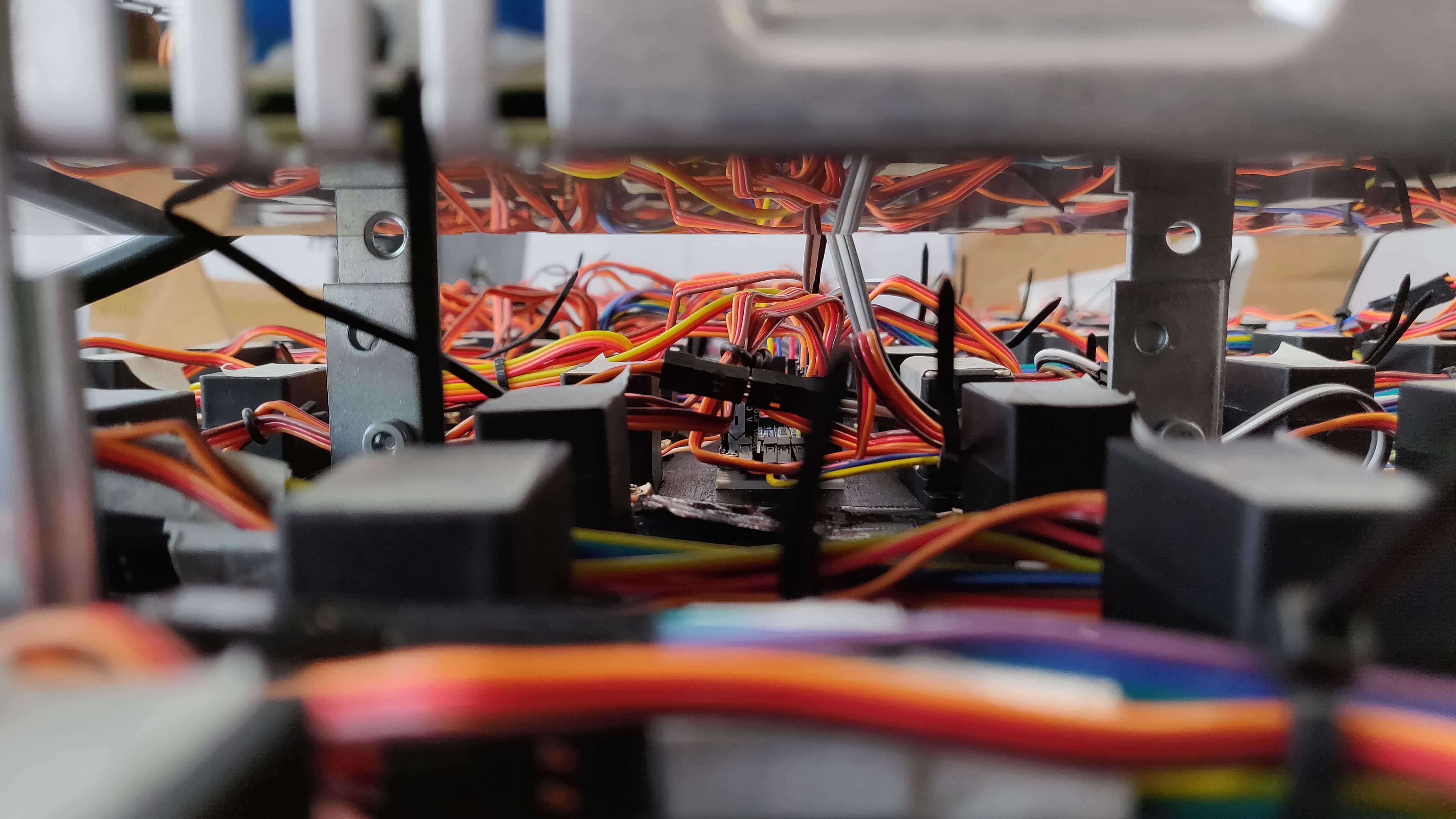
Hardware
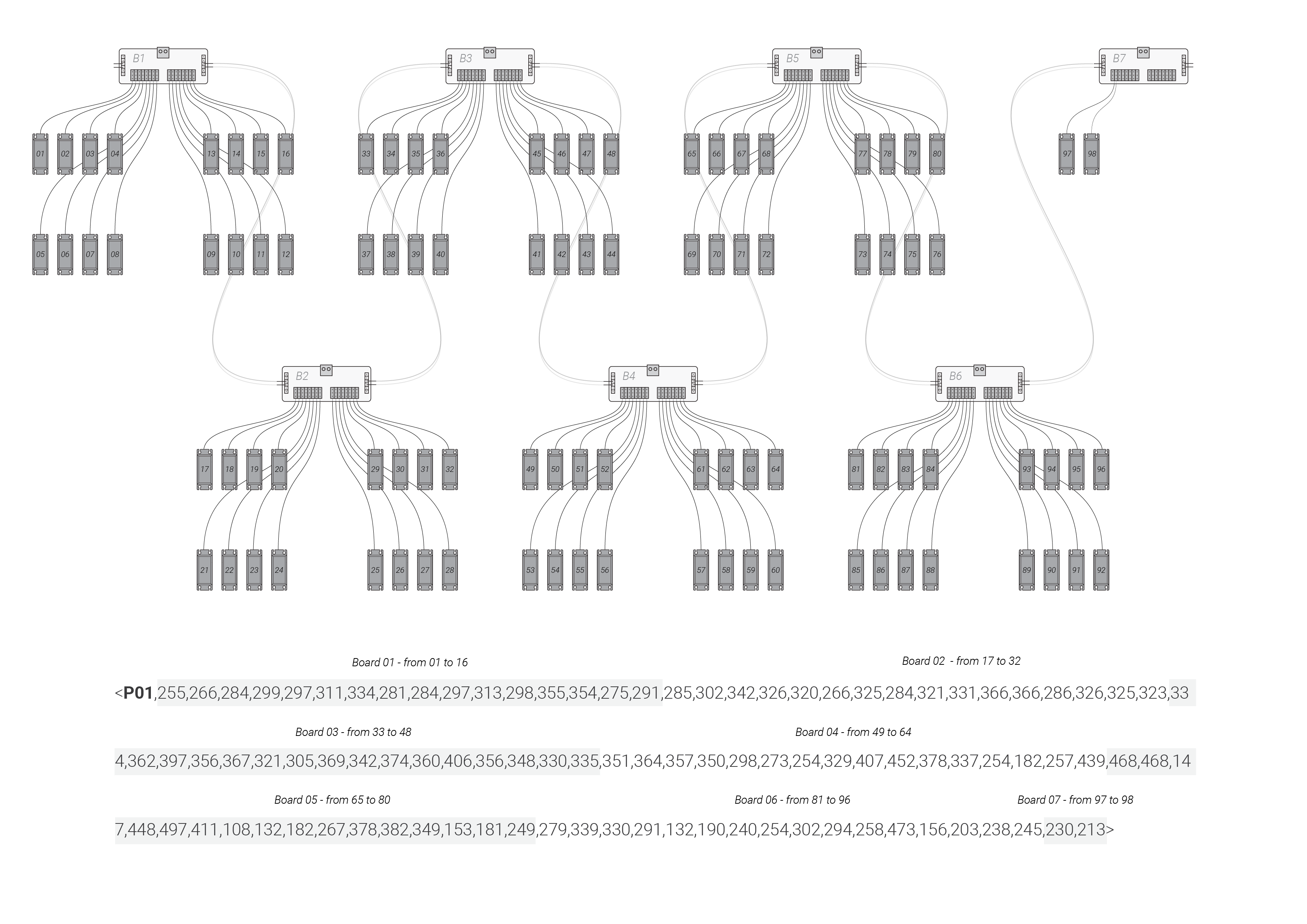
In order to standardize and allow scalability to the M.A.T.S. project the control of the servo motors was delegated to externally controllable ICs. Each of the seven expansion boards support up to 16 servo motors and are accessible from the main controller with I2C protocol. The motor matrix is mapped to a linear array of positions that is then partitioned in smaller groups of 16 values for each of the expansion boards. The system can be scaled up to a theoretical 254 boards with more than 4000 controllable motors.
Communication Protocol
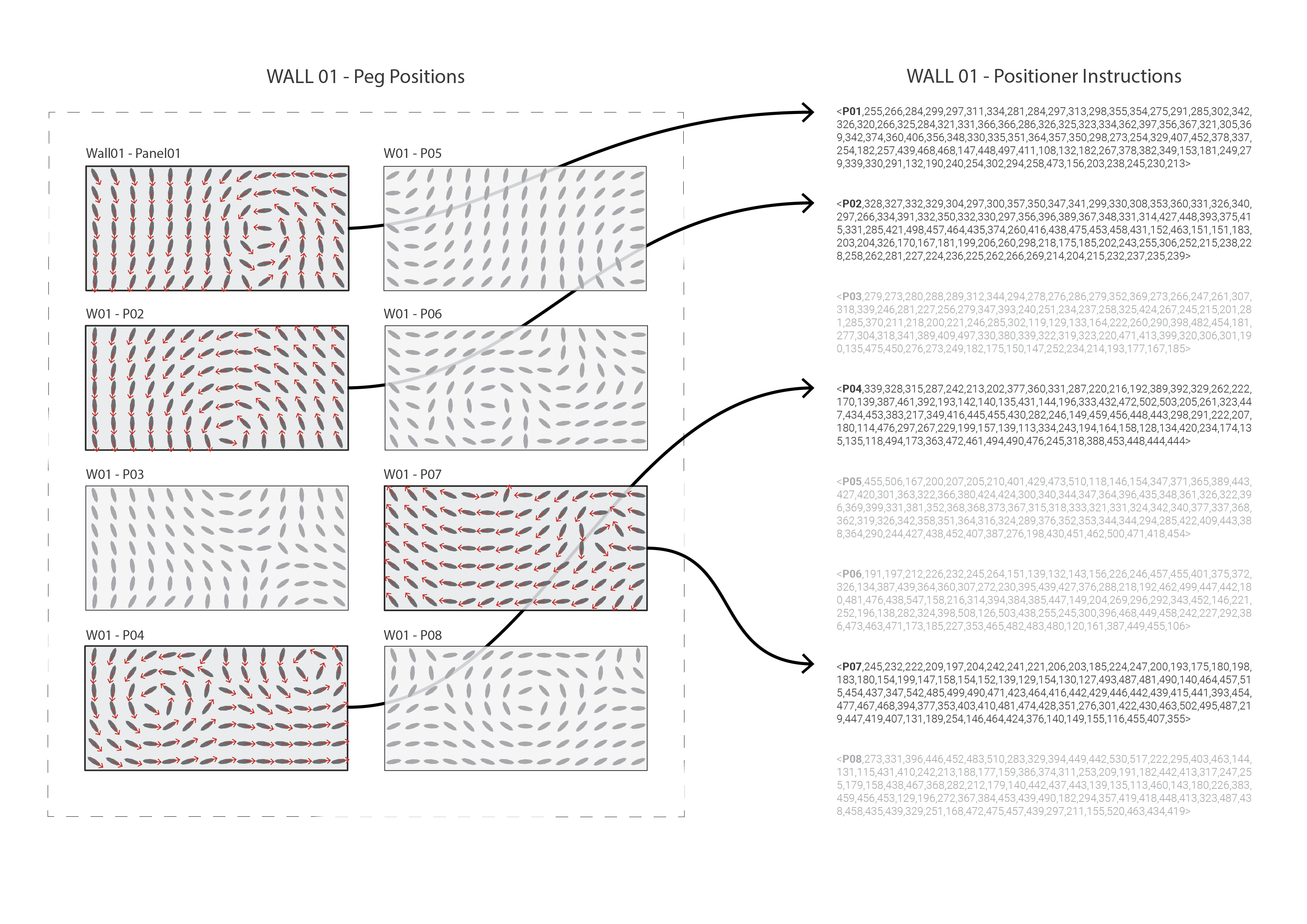
Each panel configuration is broken down into individual rotations of the 98 servo motors. The exact rotation in degrees of each peg from the home position are mapped to integer values representing the physical rotation of the motors. Due to the analog nature of the internal control unit, each motor has to be fine-tuned in order to reliably map the design rotation with the effective rotation. The control values are then wrapped in a string format with a starting unique label that identifies the panel to produce.